Sunday, February 28, 2016

Let's Build A Royal 5: Assembling the main systems (Part 3)

Welcome to the magical, wonderful world of rebuilding typewriters. Please keep your hands and legs inside the crazytrain at all times.

Picking up where we left off, you should have just finished placing your spacebar on your machine.


We now turn our attention to the ribbon drive assembly.


First, well get the left side on. The reverse L will hold the rod off to the right, and connects to the left/right lever at the top.


Youll need to unscrew the screw on the wormgear, slide the wormgear end through the hole, then reattach the screw.


Next, youll need to position the assembly into place. Youll start by positioning the small circular part above the back hole, then slip the rod into place and fasten the main hanger to the side of the frame. Ensure that the catch arms on each gear on the rod are in place to allow one-directional travel of the rod in conjunction with the main clockwork motor.


Here it is in position.


Now, we add the right side. It is far simpler of course.


Go ahead and throw the linkage on for the bichrome selector as well.


Now we add the typebar rest. It screws in from below.


Next we throw the margin-stopper for the typebars


It swings towards the back of the machine, and would in effect stand at the very tip of the typebars to stop them.


Next I threw on the shift keys. You'll need to put some pressure on the ends to get them to slip onto their linkage spots.


Now we add the second cover step, and alongwith it the tabular lever.


After you screw it in (from the outside of the frame), make sure to get its spring on as well.


Next, we throw on the bell-ringer/tabulator activator.


It goes on the right of the escapement assembly.


Go ahead and get the bell on at this point.


And get the tab linkage put into place.


I then threw in the bottom row of keys, and the backspace.


When putting on the swing-levers, make sure the small ones that connect to the plate fit into the top hole of the two on the bottom of each key lever (I messed that up here, pay no heed).


Next: Finishing the Royal 5 body

Saturday, February 27, 2016

Typewriter Reconstruction Master List


As my series on rebuilding typewriters is scattered about, I figured it would be best to consolidate the links here on a master list. Thus, here they are:


Oliver 11 Reconstruction
(Also works directly for Oliver 9's, Works 99% for Oliver 5's.)

http://wordsarewinged.blogspot.com/2015/04/do-you-want-to-build-oliver-part-1.html
http://wordsarewinged.blogspot.com/2015/04/do-you-want-to-build-oliver-part-2.html
http://wordsarewinged.blogspot.com/2015/04/do-you-want-to-build-oliver-part-3.html
http://wordsarewinged.blogspot.com/2015/04/do-you-want-to-build-oliver-part-4.html
http://wordsarewinged.blogspot.com/2015/05/do-you-want-to-build-oliver-part-5.html


Fox Portable Reconstruction
(Works for all models)

http://wordsarewinged.blogspot.com/2015/09/lets-build-fox-portable-typewriter-body.html
http://wordsarewinged.blogspot.com/2015/09/lets-build-fox-portable-typewriter.html
http://wordsarewinged.blogspot.com/2015/09/lets-build-fox-portable-typewriter_9.html


Rem-Blick (Blickensderfer 5) Reconstruction
http://wordsarewinged.blogspot.com/2015/07/how-to-build-blickensderfer-part-1.html
http://wordsarewinged.blogspot.com/2015/07/how-to-build-blickensderfer-part-2.html

Royal 5 Reconstruction
(Works for most of a Standard, 1, 2, 3, or 4 as well)

http://wordsarewinged.blogspot.com/2016/02/lets-build-royal-5-escapement-assembly.html
http://wordsarewinged.blogspot.com/2016/02/lets-build-royal-5-assembling-main.html
http://wordsarewinged.blogspot.com/2016/02/lets-build-royal-5-assembling-main_25.html
http://wordsarewinged.blogspot.com/2016/02/lets-build-royal-5-assembling-main_28.html
http://wordsarewinged.blogspot.com/2016/03/lets-build-royal-5-finishing-body.html


Thursday, February 25, 2016

Let's Build A Royal 5: Assembling the main systems (Part 2)


Broadcasted live from the land of the potato, Welcome to Words are Winged's Lets Build A Royal 5!
Where the pictures may not matter, and the process is made up!

Picking up after the last segment, you should have the main carriage shift rod in place. Now, what you'll do is unscrew the two small screws on the top left and right of the frame bar that normally holds the segment. These screws, if you look below the bar, jut out, and are used to stop the upward motion of shifting. Once out of the way, you will want to unscrew the activator piece of the ribbon vibrator, and take the small hook on the left side of the rail frame off. You should now be able to drop the escapement assembly into place, with a bit of gentle nudging here and there. Once in place, you'll place the locking bolts into position on each side. They are located...


 Here, just past the hex nut/screw. This one is already in. You will then proceed to lock the bolts in place with their respective screws.


Now, we screw in the bottom of the assembly to the arms we added last session. Note that due to the design, you may have to turn the arms hex nut a bit to get everything to work smoothly; the hole in said nut is not centered so as to allow tuning of the position of the arm.


With the machine on its back, you should see this. Once you re-tighten the screws and add the hook back on, you should also make sure that the carriage rail slides smoothly up and down. If it does not, you'll need to adjust those hex nuts.


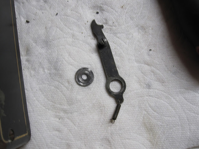
It took me a few minutes to figure out what the L shaped part was for, but I deduced its purpose; it is part of the backspace. Youll need it, the small screw, and the linkage. The key wont be put in until far later.


Here it is in position, and linkaged up. It connects to the awkward thing from last post.


Now we go ahead and add the keylever guideplateamagig.


I screwd in the front right and the back left screws, and waited to do the other two.


I'm not sure yet what this does, but I do know where it goes. It goes on the back right screw of the guideplateamagig.


Bam. Washer between it and the guideplateamagig, spring attached to small protrusion. 


At this point, if your like me, you have had just about enough of that damnable ribbon holder swinging around like it owns the joint. Thus, we add the segment. It has two emplaced rods to ensure perfect alignment. Gently push it place, then tighten the screws to perfection. Watch to make sure you get the ribbon vibrator on correctly.


Just because I could, I threw on the shifting springs for the sake of it. Watch to make sure the left side is symetrical to the right; there is another catch on the shift rod that is meant for a linkage down the road.


Now we throw on the front shift bar. It has a spring on it that will press against the front of the frame, and force the rod into its rest position. I think I turned the spring twice to give it proper pressure. To place this, unscrew one side from the frame, set the rod onto the in-place screw, then reattach the other screw.


Now, the linkages for that rod. You will need to unscrew the backspace part again, as well as the hook from last session. The smaller linkage shown below attaches the shift rod to the hook, and the larger one fits onto the previously mentioned position on the super-rod. Replace the backspace part and the hook, making sure that it clamps onto the rail frame when at rest. If not, adjust the hexnut on it, or lengthen the linkage.


Now add the first step plate. You may have to loosen the guideplateamagig to allow it to slide into position. Take care to get the guideplateamagig back into its proper position afterwards, however.


Now for the spacebar. Again, I turned the spring twice I beleive. Slide one side into the proper hole, having loosened the washer, then jimmy it so that the other end slips into its position. Having kept at least one sides washer in its original spot, youll have no issues with where the spacebar should be resting. Tighten the other washer after you move it back into place, and you should have the following.


A spacebar reaching for the stars.


Throw its linkage into place (it connects directly to the universal bar, you'll see the spot) and test that it activates the escapement when you press it. Adjust the linkage by slightly bending it if necessary.


And finally for Part 2, we add the second cover plate, which will hold the spacebar down. Your Royal 5 is starting to come together!


Next: Assembling the main systems (Part 3)

Tuesday, February 23, 2016

Let's Build A Royal 5: Assembling the main systems (Part 1)

Warning: This post contains a severe lack of pizza related topics. Reader discretion is advised.


With the escapement assembly completed, we begin on the main systems.

First, we grab the frame. Only the motor is attached currently, along with the hooks which anchor the shifting springs.

We now take the motor rod anchor, the small circle, and the most awkward collection of riveted parts I have ever seen, along with the small part shown just below them, and get them installed.


Here we have the back of the machine, and the end of the motor rod exposed. Notice the small hole on the part on the rod.

That is where the small circular part goes, and screws in. The smaller circle will just out beyond the edge of the large one just a small bit.


Then you add the small deflated balloon part.


Then the super awkward part. Note which way it goes on.


Then you add the motor rod anchor. Youll need to swing it into the frame area slightly to get it to run onto the rod right.


It screws into the back here.


Now we screw in the awkward part. You'll need to get creative to swing it into position.


It screws in here as well.


Now well go ahead and throw on the margin/margin release, and the motor tension adjuster.


The tension adjuster falls right into place. Then you add the small, longer screw.


The margin base has two pivots to stick onto, keeping it perfectly in position at all times.


You now throw on the tension plate for the margin release, screwing it in with the one small screw and the large hex screw which will later on also hold the bell.


Next youll add the carriage swing arms. You should probably throw these on earlier, as you will have to unscrew the awkward part again to get the left side in, but even still it will only take a second of your time.


Next we add the carriage locking arm. It goes on the left hand side of the machine.


Add the linkage for the margin stop.


Now we throw in the main shifting rod-a-ma-jig.


It has ball bearings, 9 on each side.


What you will want to do is screw one side it tightly while keeping the other end aligned to the hole. When done tightening, the rod should be caught in place, and allow you to place the 9 ball bearings. Using a non-magnetized philips works best for getting the bearings in their proper positions. Once in place, screw in that sides screw tightly, then flip the machine into normal position. Turning both screws slowly at the same time, making sure more to keep the ball bearings on the side you just did in place, get the other side jammed up to its spot. Take that screw out, insert bearings as before, then replace screw. Turning both again, get the thing centered with no play, but still with freedom to swing.


 Next: Assembling the main systems (Part 2)