Warning: This post contains a severe lack of pizza related topics. Reader discretion is advised.
With the escapement assembly completed, we begin on the main systems.
First, we grab the frame. Only the motor is attached currently, along with the hooks which anchor the shifting springs.
We now take the motor rod anchor, the small circle, and the most awkward collection of riveted parts I have ever seen, along with the small part shown just below them, and get them installed.
Here we have the back of the machine, and the end of the motor rod exposed. Notice the small hole on the part on the rod.

That is where the small circular part goes, and screws in. The smaller circle will just out beyond the edge of the large one just a small bit.
Then you add the small deflated balloon part.
Then the super awkward part. Note which way it goes on.
Then you add the motor rod anchor. Youll need to swing it into the frame area slightly to get it to run onto the rod right.
It screws into the back here.
Now we screw in the awkward part. You'll need to get creative to swing it into position.
It screws in here as well.
Now well go ahead and throw on the margin/margin release, and the motor tension adjuster.
The tension adjuster falls right into place. Then you add the small, longer screw.
The margin base has two pivots to stick onto, keeping it perfectly in position at all times.
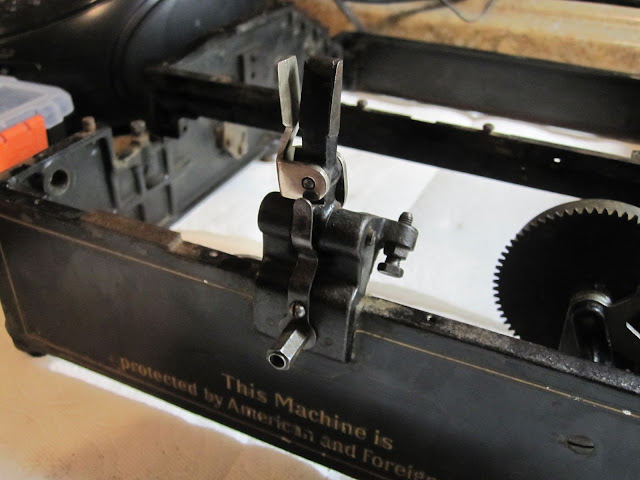
You now throw on the tension plate for the margin release, screwing it in with the one small screw and the large hex screw which will later on also hold the bell.
Next youll add the carriage swing arms. You should probably throw these on earlier, as you will have to unscrew the awkward part again to get the left side in, but even still it will only take a second of your time.
Next we add the carriage locking arm. It goes on the left hand side of the machine.
Add the linkage for the margin stop.
Now we throw in the main shifting rod-a-ma-jig.
It has ball bearings, 9 on each side.
What you will want to do is screw one side it tightly while keeping the other end aligned to the hole. When done tightening, the rod should be caught in place, and allow you to place the 9 ball bearings. Using a non-magnetized philips works best for getting the bearings in their proper positions. Once in place, screw in that sides screw tightly, then flip the machine into normal position. Turning both screws slowly at the same time, making sure more to keep the ball bearings on the side you just did in place, get the other side jammed up to its spot. Take that screw out, insert bearings as before, then replace screw. Turning both again, get the thing centered with no play, but still with freedom to swing.
Next: Assembling the main systems (Part 2)


Something tells me you're very patient and well organised. :)
ReplyDeleteIf you were to see the rest of my workbench, I believe you would quickly take back that statement... my level of disorganization borders on insanity
DeleteAs always, I am incredibly impressed by the calm, confident way you approach putting together a 100 year old machine with no manual, no diagram. I am tinkering with a margin release mechanism on a 1940 Royal Companion and I broke into a cold sweat just removing a couple screws.
ReplyDeleteOh pish posh, I think that if someone shipped you a box of parts you could piece the machine back together. Seeing the work you do, you could probably Macgyver a typewriter out of three pencils, an old rubber band, and a broken toothpick.
Delete