Wednesday, April 29, 2015

Do you want to build an Oliver? Part 4


A note first about Oliver's before we begin this shorter entry.
Oliver's, without oil, are like automobiles without petroleum. They will simply refuse to work correctly. Thus it is important to oil those parts that move, not too much not too little, and work the parts so that the oil gets into the seams it needs to be in. This is especially true after cleaning a machine as I have presented here. Of notice is the carriage assembly pivot points. Without oil, shifting will be sluggish and improper. After oiling, it will be found that shifting will spring with life, joyous to allow you to print capitals or figures. Anyway, here we are: Do you want to build an Oliver, part 4.


First up on the list is the shifting superrod. There are ball bearings on each side, 5 per side, that allow a smooth shifting experience. I prefer the Oliver 5's method, which is simply a hollowed cone-shaped end which a cone shaped screw fits in. Ball bearings here seem rather unnecessary. But here they are. So try your best to get them in their positions and gently place the bar into position, and tighten the screws.


The middle of the bar has a large jut upwards which connects to the carriage/escapement assembly. Attached point A to point B via spring plate already in position.


Now we add the space-bar assembly.


It screws into the large plate we added in the previous part. Make sure the holes align at the top of the picture so that the space-bar itself can readily be placed into position. Also make sure the hooked bit is in its place before completely screwing anything down, and ensure it is relatively firmly held against the space-bar lever.


Before we add the spacebar, we add the small decorative plate which goes right below it.


Shiny!


Now the space bar.


The underside of the machine is a bit cramped by this point, so with patience screw the nuts onto the end of the space-bar poles and ensure a firm tight connection.


Your keyboard is complete!


Now we add the piece which ensures the space-bar doesn't descend too far.


Here it is in place. Make sure it is far enough towards the back of the machine to not inhibit the space-bars normal operation.


 Ta-Da! The underside of a (for the most part) completed machine! The only things missing are the left margin lever, which I add almost last of all things for some reason, and an odd subsystem which I have no clue what it does. Ill get to that in the final part of this How To.


 However, this machine is ready to type! I grab the carriage from my Oliver 5 (Don't mind the horrid paint-job please), some paper, and a ribbon.


Olivers need their special sized wooden cores. Normal spools wont work on them, so I grab my Oliver 5 spools as well and throw the ribbon on them.


Throw the carriage on, roll some paper in, and prepare to see beautifull and perfect typing! :D


Or the chaotic mess which can be easily expected after taking a machine completely apart. After a few moments of typing, I realized that my left side keys were set improperly in comparison to the right side keys, or vise versa. To change this...


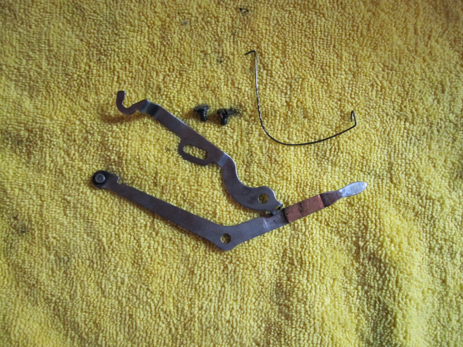
We mess with these two scews. The left, larger one locks the piece in position, and the right, smaller one actually raises or lowers the entire tower, thus tilting the type left or right.


I was able to close the gap between DD and KK, and (not pictured) made the space just a bit more between the two, bringing the two towers (after a few adjustments on the left tower as well) into position and ready to conquer middle earth.


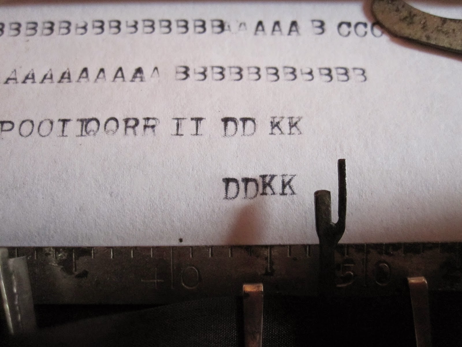
Its got impression issues as well, but by golly I was able to somewhat type that most famous line. Im talking about baabABBBAA, of course.


The carriage is just as important to the adjustment as other things. Changes must sometimes be made to this bit shown here, which rides the back rail. Raise or lower to your desire.


This means, however, that I need the Olivers original carriage to properly tune it further, so I finish off what I have on hand ready for the body, the patant plates, and prepare to dissassemble the carriage for cleaning. 


Up next: Do you want to build an Oliver? Part 5; The Finale
Where we show how to build the carriage, make tuning adjustments to set the whole machine into alignment, finally place the left margin release which should have been done sooner, make a few final additions to the machine, and bask in the glory of an Oliver 11 brought to life once more. Stay tuned!

Monday, April 27, 2015

Do you want to build an Oliver? Part 3

Welcome back to another episode of "Do you want to build an Oliver", where the rules are made up and you might just go insane.


Now that the escapement/carriage assembly is completed, we focus on the body again. Due to a broken mainspring, I had to delay attaching the motor which should have been done as the very first step out of everything. Woops. To add it at this stage, simply unscrew the plate holding the typebars in their hanger, seperate the second and third levers, and screw the motor on. You can see its two screws; one between the levers and below the spring plate, and one off to the right just above the foot.


Tidy up again, and its like we did the step correctly.


Your motor is now ready to pull its carriage.


We now add the shifting levers. The same screws that hold the lever hangers down also hold the respective spring plates down.


Here they are attached on the left side.


Repeat for the right side,


and add the springs.


Now we take the assembled carriage/escapement assembly (Anyone got a better name?), and its main hangers.


Take the top screw out from the side, and loosen slightly the lower screw, on each side.


With some careful finagling, the description of which is impossible, we place the assembly into the machine body. I forgot to place the left margin release bit, which you see dangling, in its hole. It is easy to remedy this without taking the assembly back out, and will be detailed later.


In all its glory, the Oliver starts taking shape.


After placing the screws back into the sides of the assembly and tightening the lower ones, we add the main hangers.


The assembly should now be in its fixed position. We now add the top to the roller at the back of the machine.


Zing! Sparkle Sparkle.


Now its time to flip the machine over, and add the shift locks, and automatic reverse.


The shift locks go on loosly first, after which you muscle the ribbon reverse cylinders through their holes. Run the rod through the respective holes, and tighten the shift locks and cylinder screws. 


Now we add the ribbon advancement super-plate thing which also acts as an anchor for other things.


Its main screw attaches to the roller-guide, and has a cylinder to allow the proper height. Make sure the small plate, pictured above, is in place with the small indents facing towards the back of the machine.


Now we add the automatic reverse engagements.


You'll slip them in, holding some of the typebars down, through the top plate we added as step 2 or 3 in the first section of this how to. Once they've found their way to position, you'll attach them to the cylinders you had previously left floundering on their own.


Now for the ribbonspool rod.


Before you let it this far down, ensure you have the locking cylinder and grip cylinder (not shown) on the rod. Then you can lower it in place and properly affix said cylinders to their respective locations. 


On the underside, we attach the gear to the bottom of the rod.


repeat for the other side.


Its coming together! We now add the shifting mini-rods, which connect the shifting levers (seen above the ribbon plate thingy)


We then screw the screws in, and lock the mini-rods to their position.


Now we add the universal bar.


In its natural rest position, it should lay directly atop the key levers. Screw it in towards the front of the machine. There should be two nuts, one on each side of the machine, on the inside of the screw which are then used to lock the screw in place. Make sure the little clasps are properly opened when placing this piece so they dont get caught incorrectly on the ribbon advancement gear they active.


We now add the spring which forces the universal bar to its rest position.


We connect the universal bar to the reverse T-bar. (Please disregard the two large nuts. There should only be one large nut which actually screws onto the screw shown.)


Here it is attached. The large nut goes between the two pieces, the square inside the t bar itself, and the washer/small nut on the outside to lock the whole thing in place. Ensure it is tight, but not restricting movement of the entire mechanism. Its a bit finicky.


Now we add the lever which stops ribbon movement between spools. Why this is needed, I don't know. But its there to be used regardless.


This may be easier to do earlier, but it posed no true problems getting it in at this stage. Just finagle the lever piece in however you must.


For all intents and purposes, this machine is able to type. One long, long word, due to the absence of the space bar. And it cant shift quite yet. But that aside, a mono-word letter to your friend may be in the works.

Congratulations, your almost there!
Up next, we add the shifting rod (hopefully) and the space-bar, the ribbon-cups, and the left-margin release, and begin the fun process of adjusting the machine!