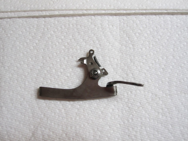
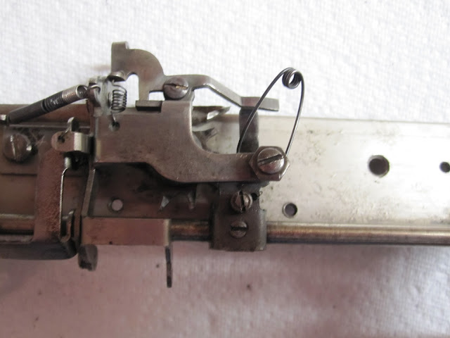
As some of you may know, there are 3 models of Fox Portable Typewriters. The No. 1, No. 2, and Sterling (also known as No. 3, as seen on its front plate). There were roughly 10,000 No. 1's made, roughly 2,000 No. 2's, and roughly 1,000 Sterlings (Known serial numbers go above 13,000, but not by much).
All of them have the same design for the main body of the machine, as detailed in the previous post, save for a small few changes to help make things run just a bit smoother. The carriage is a different matter, however. The No. 1 is entirely different then the No. 2, though the No. 2 and the Sterling share the exact same design. One of the most noticeable changes is the complete re haul of the escapement system.
On the No. 1 the escapement is a very simple design, and is prone to issues from friction. The No. 2 improved the concept by redrawing the whole thing, and having it be a standalone piece that could be manufactured separately from the rest of the carriage, thus making assembly quicker.
Detailed here below is, first, the escapement of the No.2/Sterlings, then the No. 1's escapement will be looked at.
Let us begin.
Here is the base escapement frame of a No. 2.
And here are all the parts necessary to build a carriage altogether.
We begin by adding the margin stop/release.
Next we add the escapement release action.
Next the ribbon vibrator activator. It slides in on one side onto a small screw already present, then the other side must be screwed in.
This is the second part of the ribbon vibrator system, which will slide into a hole in the frame on the one end. Connect the spring from the first piece to the hole here once its screwed in.
Now we add the actual escapement dog action piece.
Now we can add the bell ringer
And the tension spring which keeps the margin stop/release in its place until otherwise activated. I forgot the picture for this one, so in the above picture it will screw into the hole prominently shown between the bell ringer and the right "tower".
Your escapement for the No. 2 is now completed (I forgot the picture. again. Woops. You can look at the almost completed picture to understand what it looks like though.)
Now we begin to assemble the No. 1 carriage. As you can maybe tell, it was a last second thought and thus randomly scattered.
Taking the main carriage frame itself, we add the ribbon movement arms.
Then we add the carriage lock, for when the carriage is set down and the machine is placed in its case.
Now the escapement outer-frame. The wheel is already in the carriage frame, being un-removable by conventional means. This piece is made up of 4 other pieces; a small levered bit for the escapement release, seen on the far left, the body of the piece itself, and two lever pieces for the ribbon vibrator seen towards the center. The tension spring you see will hold down the dogs added later.
For now I only lock one screw in place, because...
We now want to add the backspacer.
You'll want to set the area between the two "teeth" on the lever in the gap provided for the lever on the body of the escapement frame thing.
Now we add the action rod, with the dog attatched.
There are two small screws, one on each side of the frame, which will hold the rod in place. The escapement will look like this once its all in place.
Now we do the tricky part; getting the carriage on its rail. Ball bearings? prepare yourselves, chaos will reign until you somehow get lucky.
What I like to do is get one of the carriage sides screwed, tightly on one screw, looser on the other. That way i have a pair of "scissors" per say.
With one side of the carriage rail angled up, youll want to add the ball bearing or bearings (two on the front, one on the back) for that side and carefully place the open-scissor carriage on it/them. Make sure its centered when you do this to make it easier. Then, holding the side already done very, very firmly in a death grip, flip it over and add the final bearings, and snap the scissors shut. Then, holding the whole thing together, tighten the heck out of the screws on the side piece, and begin screwing in the main attaching plates with the 6 screws previously removed.
You'll need to carefully change the spacing of the two carriage main pieces, so that when holding the escapement release, the carriage rides smoothly from one end to the other, and back again. Smooth with not a single hiccup or catch (The carriage lock might interfere; this is ok, just push it out of the way if possible for now for testing purposes.).
Now is the time to tune your escapement, after screwing everything in nicely. The two small screws in the center (Disregard the bottom most screw) are the primary means of adjustment, along with the screws holding the rod in. I spent roughly an hour and a half tuning this precisely due to an odd ammount of friction being present, causing a loud grinding. You may not have to mess with these screws at all if your lucky.
That concludes this portion of Lets Build A Fox Portable Typewriter. Coming next, we finish the carriage of the Fox No. 1, and tune the overall machine. (The No. 2 after the escapement is fairly similar, and thus wont be shown lest otherwise demanded).


Absolutely amazing! Thank you for sharing this.
ReplyDeleteAre we going to find out that you are actually a 120 year-old former Fox Typewriter Company quality assurance engineer typing from a retirement home in Grand Rapids, Michigan? Thank you for another fascinating and useful post.
ReplyDeleteWow. This is the kind of stuff that makes me VERY nervous. Hats off to you, and thanks for documenting this for the world!
ReplyDeleteThank you for taking the time to show your process! (BTW, I read your reply about making your own machine in the future: taking preorders yet???) :) Great, great work as always!
ReplyDelete